 Mechanism of the Full-Scale Seismic Isolation Testing Machine
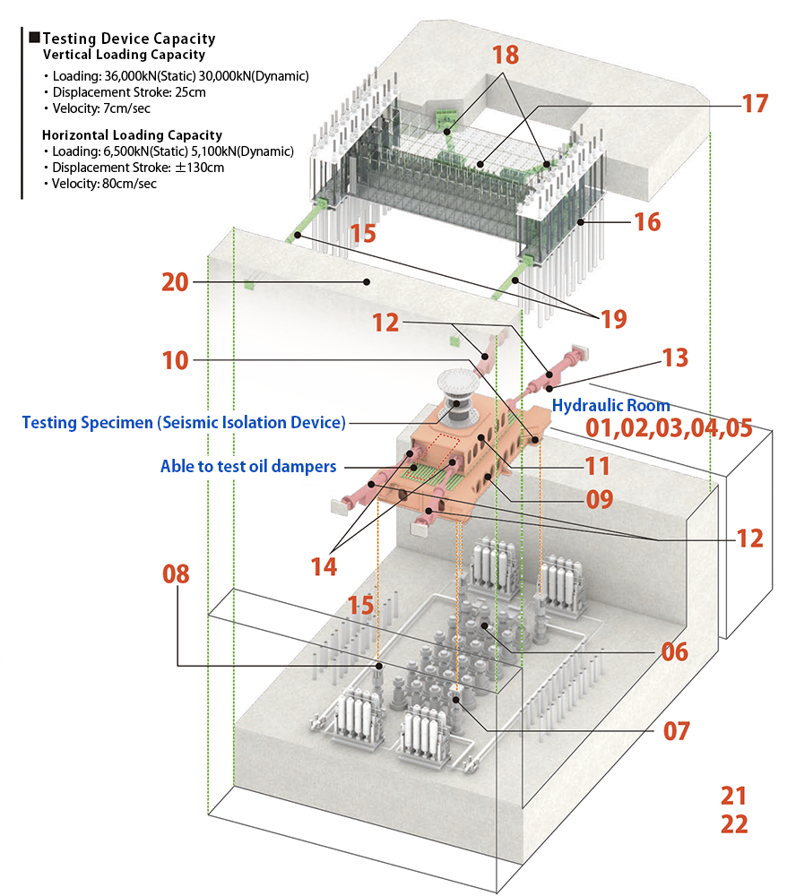
We define the loading direction as the x-axis, the vertical direction as the z-axis, and the direction orthogonal to both as they-axis. In three-dimensional space, the upper reaction beam (17) must be constrained in all six degrees of freedom (three translations and three rotations). The upper moving platen(11) rides on linear bearings on the lower moving platen and moves rapidly left–right in the x-axis direction, while being free to translate in the z-axis direction. In three-dimensional space, its translation in the y direction and all three rotational components must be constrained.
By clicking (o, a, b, c, d, e) in the overview diagram, you can view photographs of each part. Click (o) to return to this page.
<Vertical Jack and Lower Moving Platen>
The vertical dynamic jacks (06), also referred to as vertical actuators, can apply a dynamic compressive load of 2,000kN per unit. With 24 units installed (4 × 6), the total capacity is 48,000 kN, which provides ample margin for actual tests. The cylinder feet of the jacks are fixed to the top surface of the foundation mat, which is a 4,500 mm thick prestressed concrete slab. The internal pistons move upward, with rods connected above them; at the rod tops, load cells are installed for force measurement. The lower moving platen(09), a rigid structure, is supported via a spherical bearing and a flat sliding bearing. The lower moving platen is subjected to upward forces from the vertical jacks and downward forces from the test specimen and consequently undergoes curved (dish-like) deformation. The spherical and flat sliding bearings are provided so that deformation of the lower moving platen does not impose undue constraint on the jack motion.
Because these two bearings do not restrain in-plane deformation, the lower moving platen is unconstrained in x, y, and θz. To restrain these, stopper side rollers are installed at the four corners of the lower moving platen table, allowing only vertical movement. Additionally, to restrain the two rotational components θxand θyand to ensure that the lower moving platen can move up and down while maintaining parallelism, parallel-maintaining device in vertical motion (07) are installed at the four corners. Each of the device has hydraulic chambers above and below its piston. The upper and lower chambers are cross-connected under high pressure to the diagonally opposite parallel-maintaining jack, with the connections inverted (upper-to-lower, lower-to-upper). This creates the same effect as a drafting parallel ruler connected by wires, ensuring that the lower moving platen maintains parallelism andmoves only vertically.
<Horizonal Dynamic Jack>
Also referred to as horizontal actuators. To ensure stable in-plane motion, four dynamic jacks are installed in a V-shaped arrangement rather than parallel, similar to the SRMD dynamic testing machine at the University of California, San Diego. The horizontal jacks provide large motion within a maximum displacement of ±1,300 mm and a maximum speed of 800 mm/s. The rods attached to the pistons inside the cylinders are present only on the shaker-table side; there are no rods on the reaction-wall side. The pressure-receiving area of a piston under hydraulic pressure is exactly half on the rod side compared to the rod-less side, so the force generated during rod extension is large, while the force during rod retraction is half. The combined forceofthe four horizontal dynamic jacks installed on the left and right sides of the upper moving platen acts on the test specimen.
<Reaction Wall and Reaction Beam>
A rectangular reaction wall is constructed on the 4.5 m thick foundation mat. It is a robust 3.5 m thick prestressed concrete structure, with ample reinforcement provided in both directions and sufficient prestress introduced. On the north and south reaction walls, 12 Elastomeric Rubber (16) with high vertical stiffness and sufficiently low horizontal stiffness are installed, and the reaction beam is placed atop them. These are clamped with more than 50,000 kN of tension using 48 bundles of PC steel strands—each bundle consisting of twelve parallel seven-wire strands (φ12.7), giving an outer diameter of 85 mm (16)—extending over a length of more than 14 m from the underside of the reaction wall foundation mat to the top surface of the reaction beam. Through this arrangement, the reaction beam is firmly restrained in the z direction and about the x and y axes (θx, θy). In contrast, it is elastically supported in the x and y directions and about the z axis (θz) with small horizontal elastic stiffness, which is the sum of the shear stiffness of the 12 elastomeric isolatorsand the geometric stiffness due to the change in orientation of the vertically installed PC steel strands.
When a test specimen is installed between the upper moving platen and the reaction beam, and a large compressive load is applied during testing (for example, 30,000kN), an upward force acts on the reaction beam. The prestress initially introduced into the 12 elastomeric isolatorsand the reaction wall is reduced by 30,000kN to 20,000 kN.At this time, the 12 elastomeric isolatorselongate by about 1 mm, but a large residual compressive force remains. Similarly, the compressive force due to prestress in the rigid reaction wall decreases to about 20,000kN, and the top surface of the reaction wall undergoes slight upward elongation. However, because the reaction wall’s cross-sectional area is sufficiently large, the upward deformation is negligible.
Although the reaction beam appears to pull up the PC steel strands at both ends when subjected to upward force, the actual load path is that the upward force is transmitted through the reduction in the initial compressive force of the 12 elastomeric isolators. The total length of the PC steel strands is 14 m, so the tensile strain is extremely small, and the axial force in the PC strandschanges very little. This leverages the advantageous characteristics of prestressed concrete structures.
<Measurement Link>
Measurement Links Similar to the V-shaped horizontal dynamic jacks, two high axial-stiffness steel tubes (18) equipped with 4,000kN load cells are installed in a V-shaped configuration, extending from the rigid reaction wall through the centroid of the reaction beam’s plan. These elastically restrain the reaction beam in the x and y directions. By connecting these measurement links at the height of the lower flange, the twisting moment aboutthe y-axis induced in the reaction beam by the specimen’s shear force is minimized. Furthermore, two parallel measurement links (19) with lower axial stiffness, each equipped with 1,500kN load cells, elastically restrain the reaction beam about the z axis (θz).
At both ends of these four links, ultra-high-strength steel is used, and the cross-sectional area is reduced with plate-like or cylindrical shapes to lower bending stiffness. Because the end connections are not mechanical pin joints, there is no axial play, and the ends are made more flexible in bending. As a result, bending stresses induced in the load-cell sections by minute displacements of the reaction beam are minimized.
(o、a、b、c、d、e) |
|